Privacy policies
GDPR data Terms of use Cookies policy Privacy policy Delivery and Payment How to order?
Privacy policies
GDPR data Terms of use Cookies policy Privacy policy Delivery and Payment How to order?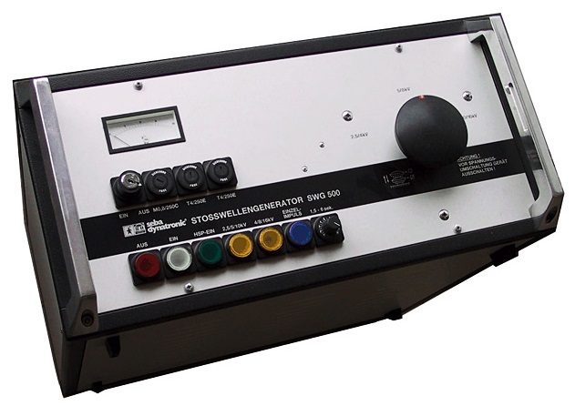

Code: Seba-KMT SWG-500 SWG500
 Datasheet
 PDF, 1.4 Mb
Description
The Surge Wave Generator SWG 500 operates in the middle voltage range of the usual SWG’s while its surge energy is in the lower range, The three voltage ranges are switchable and allow for each voltage stage the full surge energy of 500 Joule.
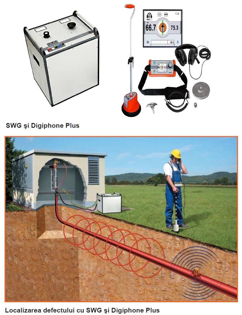
In combination with the digiPHONE+, the 500 Joule surge energy of the SWG 500 becomes a completely sufficient solution for most of the applications.
Together with reflectometers, surge generators are the central
component for cable fault location. They are used for both prelocation
and also pinpoint location.
Prelocation
Prelocation can be divided into transient methods and Arc
reflection prelocation, which differentiates between passive,
semi-active and active methods.
ICE - Impulse Current Method
(ICE-Method = Impulse Current Equipment)
This method is ideal particularly for fault location in long ground
cables and wet splices.
The surge wave generator ignites an arc at the fault. This
results in a transient, i.e. a spreading and repeatedly reflected
travelling wave between the fault and the surge wave generator.
An inductive coupler records this transient wave with a
reflectometer, the Teleflex. The length of one full oscillation
wave corresponds to the direct distance to the fault.
A coupler for recording the transient current wave is fitted as a
standard feature in all surge wave generators with a surge
energy of 1000 J or more.
ARM - Arc Reflection Method
(HV-supported reflection method)
All reflection prelocation methods offer the advantage of a very
detailed measurement result corresponding in principle to the
picture of a normal reflection measurement. So these are the
preferred fault location methods. Differences arise with the
different technologies, which can have a relatively simple
structure resulting in weight advantages. More complex technologies
are more efficient, but also have to be integrated in a
measuring system.
The simplest method is the passive ARM method (used to be
called arc stabilization or short-term arc method). This extends
the discharge of the surge generator and with it the burning
duration of the arc by means of a series resistor in the
discharge path.
In the semi-active ARM method, the discharge is extended
by an inductivity. Use of inductivity means that the level of
voltage is not affected, making it much easier to locate faults
also with a high ignition voltage.
With the LSG 3-E, SebaKMT offers an active ARM method
with an integrated 2 kV surge unit for excellent extension and
stabilization of the arc. At the same time, this device permits
an independent use as a 2 kV prelocation and surge unit.
Pinpoint location
For a precise location of the fault it is essential to confi rm its
position along the cable, because pre-location with the Telefl ex
only visualizes the absolute distance. But the position and path
of the cable in the ground, and thus the actual position of the
fault, is only relatively inaccurately known. An absolutely precise
pinpointing is necessary to limit expensive excavation
work and resulting surface damage to an absolute minimum.
Here, a direct discharge of the surge generator produces an
arc at the fault position. The direct connection means that this
discharge takes place very quickly, generating a loud fl ashover
sound which can be located without any problems using a
corresponding acoustic receiver at the surface, such as the
digiPHONE+.
It is important to always use the maximum available surge
energy, given the proportional behaviour of volume and
discharge energy. All SebaKMT SWG surge wave generators
have switchable surge stages.
The basic equation of the surge energy is: W = 0.5 x C x U²
Example with a required surge voltage of 8 kV: The full 1000
Joule surge energy is obtained with 100% surge voltage in the
8kV surge range. A setting of 25% surge voltage in the 32 kV
surge range ( kV) would be useless, producing only 62 Joule
surge energy.
Therefore it is always recommended as follows: First select the
optimum range, i.e. the lowest necessary voltage level, and
then adjust the SWG to the maximum possible voltage. This is
the only way to guarantee the maximum energy and sound at
the arc. If only half the voltage range is used, then only one
quarter of the surge energy is available.
digiPHONE+ - receiver for combined acoustic and
electromagnetic pinpoint location
The digiPHONE+ works according to the principle of the
coincidence or difference method. It automatically measures
the time differencebetween the electromagnetic signal of the
surge voltage and the acoustic bang of the arc fl ashover.
The digiPHONE+ operates like a stopwatch. The electromagnetic
pulse starts a counter and the much slower propagating
sound stops the counter afterward. The displayed time, or the
time difference between the sound and the magnetic pulse,
corresponds to the distance to the fault. The shorter the time,
the closer you are to the fault. The display shows the difference
in time as a numerical value, while a bar graph shows the
electromagnetic fi eld strength. The fi eld strength display also
acts as a locating facility of the cable position. The bar graph
display is broken down into individual segments to permit a
very accurate defi nition of where the cable is running. As long
as you keep your bearings on this maximum, your longitudinal
axis is already exactly on top of the cable. As a result, the
position over the cable is so precise that you almost cannot
miss the fault, even when faults are very diffi cult to hear.
This location principle also works for secondary noises and is
particularly useful in situations where cables are installed in
protective ducts or under solid road surfaces (concrete,
asphalt, etc.).
Standard accessories
Recommended options
More products SEBAKMT

SEBA KMT HPG 50..80-D DC & AC HIGH VOLTAGE CABLE TESTER
• HPG 50-D, AC testing up to 35 kVRMS/ DC testing up to 100 kV |
SEBA BPS 5000-D BURN AND PROOF TEST SYSTEM ON MEDIUM VOLTAGE CABLES BPS-5000D BPS500D BPS 5000D-VLF
• Easy-go single button operation |
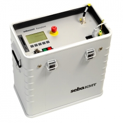
SEBA KMT EASYTEST 20KV VFL CABLE TESTER VERY LOW FREQUENCY
• simplified version of the standard VLF test |
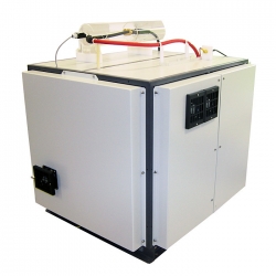
SEBA KMT VFL CR-80 46KV HIGH VOLTAGE CABLE TEST SYSTEMS
• Powerful 0.1 Hz VLF test system |
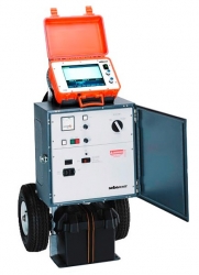
SEBA SURGEFLEX SFX-15 SFX-25 CABLE FAULT LOCATING SYSTEM
• » DC-Testing up to 15 kV / 25 kV (depending on model) |
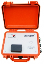
SEBA TELEFLEX LV MONITOR CABLE FAULT LOCATION SYSTEM WITH MONITORING MEGGER
• Fault location on live low voltage cables |
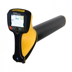
SEBA KMT VLOC-5000 LINE LOCATION AND TRACER FOR UNDERGROUND PIPES AND CABLES
• Precise direction guidance with right/left arrows and guidance compass |
SEBA TELEFLEX-VX ADAPTER FOR SAFE OPERATION OF REFLECTOMETERS ON OVERHEAD LINES
• Very easy to operate |
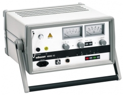
SEBA KMT MMG 10 CABLE SHEATH TESTER
• Adjustable current limiter |
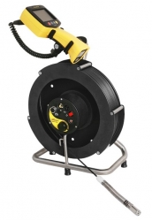
SEBA KMT VCAM LSR SEWER PIPELINE VIDEO INSPECTION CAMERA
• Flexibility, allowing multiple uses |