Description
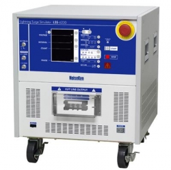
Surges represent transients that might be induced in cables by lightning. By their nature, fairly high energy charges may easily damage or upset unprotected electronics circuits and components. Surges are not a new problem. Many companies have been testing their products at various stages of the products life: design tests, qualification tests, production tests and diagnostic tests.
The advance of surge suppression devices and technique does not lessen the importance of surge testing, but rather increases it, as the requirement to reduce power consumption and to increase the operational speed of semiconductors has become more demanding. In addition, the issue of surge testing is attracting renewed interest since this form of immunity is now a must for almost all electronic products for access to the global market.
-
"Output voltage 15kV, current 7500A" which can conduct breakdown resistibility test
-
"50% reduction of the output interval" which can drastically reduce the test time
-
"Touch-panel" adopted for the easy test setting
-
"Multi-languages" for the easy operation processing available
-
"Indicator" which is linked with the test setting equipped
-
PC control available with the optional software
-
"Emergency stop" & "Interlock terminal" which secure the test operator equipped
-
"Output waveform monitor terminal" which can ease pre-checking of the waveforms prior to the actual test
SPECIFICATIONS
Surge Generating Unit
|
Parameter |
Specifications |
Remarks |
|
1.2/50µs-8/20µs
Combination waveforms |
Output voltage 0.5kV to 15kV ±10%
Front time 1.2µs ±30%
Duration 50µs ±20%
Output current 250A to 7500A ±10%
Font time 8µs ±20%
Duration 20µs ±20% |
Common for the all models
Voltage step : 0.1kV step
The setting can be from 0kV |
|
10/700µs-5/320µs
Combination waveforms |
Output voltage 0.5kV to 15kV ±10%
Front time 10µs ±30%
Duration 700µs ±20%
Output current 12.5A to 375A ±10%
Front time 5µs ±20%
Duration 320µs ±20% |
Models: C1/C3
Voltage step : 0.1kV step
The setting can be from 0kV |
|
Output polarity |
Positive / Negative |
|
|
Interval |
10 sec. to 989 sec., depending on the set voltage 10 sec. (<6kV) |
15 sec. and over in 10/700 µs waveform |
|
Output impedance |
1.2/50µs waveform : 2O ±10%
10/700µs waveform : 40O ±10% |
|
AC/DC CDN
|
Parameter |
Specifications |
Remarks |
|
Coupling surge waveform |
1.2/50µs-8/20µs combination waveforms |
|
|
Max. coupling surge voltage / current |
Up to the values which can be set |
|
|
Coupling network
Correspondent to IEC61000-4-5 |
18µF: Between LINE - LINE (10O +9µF selectable) |
|
|
10O: ±9µF Between LINE - PE (18µF selectable) |
|
|
Injection mode |
Between LINE - LINE, Between LINE - PE |
|
|
Power supply lines structure for EUT |
Single phase AC: L/N/PE
DC : +/-/PE |
Models : A1 / C1 |
|
3-phase AC : L1/L2/L3/N/PE (Common for single phase and 3-phase)
DC : +/-/PE |
Models : A3 / C3 |
|
EUT power capacity |
AC240V/20A MAX. 50/60Hz, DC125V/20A MAX |
Models : A1 / C1 |
|
AC500V/50A MAX. 50/60Hz. DC125V/50A MAX |
Models : A3 / C3 |
|
Decoupling coil |
1.5mH |
|
|
Phase angle control |
0 to 360° ±10° |
|
CDN for Telecom lines (Only in models C1 and C3)
|
Parameter |
Specifications |
Remarks |
|
Coupling surge waveform |
1.2/50µs-8/20µs combination waveforms 10/700µs-5/320µs combination waveforms |
|
|
Max. coupling surge voltage / current |
Up to the values which can be set |
|
|
Impedance matching resistors |
40O |
80O per 1 line at 2 lines
160O per 1 line at 4 lines |
1.2/50 µs waveform |
|
25O |
0O per 1 line at 2 lines
100O per 1 line at 4 lines |
10/700 µs waveform |
|
Coupling mode |
Common mode / Normal mode |
|
|
Coupling network |
Gas arrestor : 90V |
|
|
Line for EUT |
2 lines / 4 lines DC50V/100mA MAX |
Selectable |
|
Decoupling coil |
20mH |
|
Others
|
Parameter |
Specifications |
Remarks |
|
Voltage monitor |
BNC output, 1/2000±10% |
In open-circuit for SURGE OUT |
|
Current monitor |
BNC output, 1mV/A±10% |
In short-circuit for SURGE OUT |
|
External communication |
RS-232C optical communication |
|
|
Power supply |
AC100V to AC240V ±10%, 50Hz / 60Hz |
|
|
Dimensions |
W555×H1800×D790 mm |
Projection excluded |
|
Mass |
Approx. 300kg |
Models: A1 / A3 |
|
Approx. 340kg |
Models: C1 / C3 |
SELECTION GUIDE TABLE
|
Model
LSS-F02 |
Output waveform |
AC/DC Power Line CDN |
Telecom Line CDN |
|
1.2/50 µs
(8/20 µs) |
10/700 µs
(5/320 µs) |
Single phase
AC240V/30A, DC60V/20A |
Single and 3-phase
AC600V/50A, DC60V/20A |
DC50 V 100mA |
|
A1A |
Available |
|
Available |
|
|
|
A3A |
Available |
|
Standard accessories
STANDARD ACCESSORIES
|
Items |
Specifications/FUnctions |
Quantity |
Correspondent models |
|
Surge output cable |
HOT/COM |
2 pcs. |
A1/A3/C1/C3 |
|
Output cable to power supply lines |
For single phase : L / N / PE |
3 pcs. |
A1/C1 |
|
For 3-phase : L1 / L2 / L3 / N / PE |
5 pcs. |
A3/C3 |
|
Output cable to telecom lines |
For 1 to 4 lines and GND |
5 pcs. |
C1/C3 |
|
Arrestor unit |
For coupling : Equipped to main unit panel |
4 pcs. |
C1/C3 |
|
For input protection : Equipped to main unit panel |
4 pcs. |
|
Cable for monitor |
BNC-BNC cable |
1 pc. |
A1/A3/C1/C3 |
|
External interlock connector |
5P plug (Short between #1 - #3) |
1 pc. |
A1/A3/C1/C3 |
|
Power supply cable |
For AC100V, 3P equipped with G connector cable |
1 pc. |
A1/A3/C1/C3 |
|
High voltage connector cap |
Equipped to main unit panel |
5 pcs. |
A1/C1 |
|
7 pcs. |
A3/C3 |
|
FG cable |
For grounding the body |
1 pc |
A1/A3/C1/C3 |
|
Instruction manual |
In Japanese/ English |
1 each |
A1/A3/C1/C3 |
More products NOISEKEN
VOLTAGE DIP AND SWELL WAVEFORMS SIMULATOR NOISEKEN VDS-2002
• Conforming to IEC 61000-4-11 • Fully compliant with all the test generator requirements of IEC standard. • One unit solution for dip, swell, interruption and variation tests up to 16A 290V single phase AC • Interruption test up to 16A 125V DC (*) • Two motor-driven transformers approach enables switching between any voltages (*) • Preset IEC test levels 0%/40%/70%/80% plus additional 120%
|
SOURCE-VOLTAGE DIP AND SWELL SIMULATOR NOISEKEN VDS-1007/ 2007
• VDS-1007 : 1kVA Power • VDS-2007 : 2kVA Power • Enable to enrich EMC preliminary tests with the remote control as an AC stabilizing power source • Enable IEC61000-4-11/13/14/28 precompliant tests • Usable to be power source for IEC61000-3-2-2 precompliant measurement
|
ESD ELECTROSTATIC DISCHARGE SIMULATOR NOISEKEN ESS-2000AX
• 0.20kV~30.0kV Output voltage range • Fully programmable menu-driven simulator providing three operation modes: IEC standard, Manual and Sequence • 5.7-inch color LCD for easy setting and good visibility • Unique shape for the operator's easy access to the controls and displays even when the unit is put on the floor level (ground plane) • Communications with PC through the optic serial interface • wide variety of the dedicated options
|
LIGHTING SURGE SIMULATOR NOISEKEN LSS-6230
• Lightning Surge Simulator conforming to IEC61000-4-5 ed2 Standard • Ring wave conforming to ANSI/IEEE C62.45 available • Max. voltage 6.6kV output focusing on the practical use • Monitor terminal standard equipped so as for easy waveform pre-checking • Interlock built-in as the emergency stop function for safety
|
PCB BOARDS RADIATION EMISSIONS MEASUREMENT SYSTEM NOISEKEN EPS-6000
• Measurable up to 8GHz in the frequency range • 4 axes (X, Y, Z, ?) measurements with minute step minimum 0.1m realized • Equivalent distance measurement to parts on PCBs even the heights are different • Composite figure of photo of the measured PCB and the measurement data realized • Rich magnetic field probes in the figures, sizes and Vertical/Horizontal directions • Versatile display for the measurement data as 2 dimensions, 3 dimension, and equiangular line realized
|
RF EMISSION RADIATION PRECISION SCANNER NOISEKEN EPS-3007
• Provides an amplitude versus frequency plot for each antenna probe position and field intensity distribution map by a single scan • Electric and magnetic fields are separately detected • 3D graphical representation and zoom capability for a given area • Comparison before and after a modification or improvement • Scanning by a single antenna probe to minimize error between each measurement point • 3GHz maximum frequency response (option) • Standard included three kinds of antenna probes (Probe A, Probe B and Probe C)
|
HIGH VOLTAGE LIGHTING SURGE SIMULATOR NOISEKEN LSS-F02
• "Output voltage 15kV, current 7500A" which can conduct breakdown resistibility test • "50% reduction of the output interval" which can drastically reduce the test time • "Touch-panel" adopted for the easy test setting • "Multi-languages" for the easy operation processing available • "Indicator" which is linked with the test setting equipped • PC control available with the optional software • "Emergency stop" & "Interlock terminal" which secure the test operator equipped
|
IMPULSE NOISE SIMULATOR EMC TESTING NOISEKEN INS-4020/ 4040
• INS-4020 (2kV) : 0.01 ~ 2.00KV ±10% with 50 ohm load, 10V step • INS-4040(4kV) : 0.01 ~ 4.00KV ±10% with 50 ohm load, 10V step • Automatic ramp operation for output voltage, phase angle and repetition period • Floating output • Coupling mode selection by plugging the supplied coaxial connector to the selected port • Easily changeable mercury relay unit
|
|