Privacy policies
GDPR data Terms of use Cookies policy Privacy policy Delivery and Payment How to order?
Privacy policies
GDPR data Terms of use Cookies policy Privacy policy Delivery and Payment How to order?Code: Micronix MY1515
Description
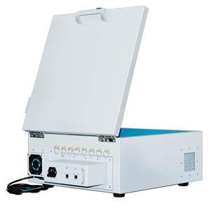
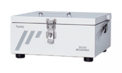
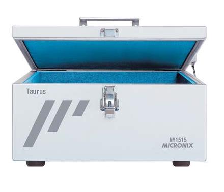
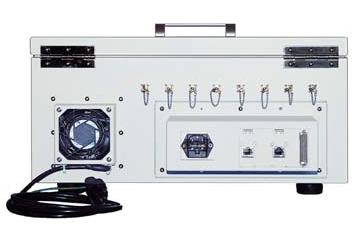
Model MY1515 Type equipping with exhaust fan and intake
Outside dimensions
Inside dimensions
Weight approx.
Shielding characteristics
Reflection loss
Fan
Connectors
I/F Module installation capacity
465(W)�465(D)�214(H)mm
400(W)�400(D)�150(H)mm
10kg (without I/F Module)
more than 60dB @ 2.4GHz
more than 20dB @ ? 2.4GHz, MYA-75
0.46m3/min
(the maximum force of the wind @ 50Hz)
8 pcs of SMA @ back
1 module @ back
Recommended options
|
Small size (MY1510) |
I/F Module |
|
Medium size (MY1520) |
I/F Module |
|
Wooden table | |
|
Radio wave absorber(MYA-77) | |
|
Radio wave absorber(MYA-79) | |
|
Large size (MY1530) |
I/F Module |
|
Wooden table | |
|
Turn table unit | |
|
Radio wave absorber(MYA-75) | |
|
Radio wave absorber(MYA-79) |
The I/F module is a module on which AC supply, DC supply, LAN, USB, SMA, BNC, N, Triaxial and/or D-sub connectors are mounted. All of the I/F modules are common to Taurus series.
|
Option |
Mounted connectors |
|
IFM1 |
IFM1 AC(1pc), LAN(1pc), USB(1pc), D-sub9pin(1pc) |
|
IFM2 |
IFM2 AC(1pc), LAN(2pcs), USB(2pcs), D-sub9pin(1pc) |
|
IFM3 |
AC(1pc), LAN(2pcs), USB(2pcs), D-sub25pin(1pc) |
|
IFM4 |
DC(1pc), LAN(1pc), USB(1pc), D-sub9pin(1pc), D-sub25pin(1pc) |
|
IFM5 |
SMA(2pcs), BNC(2pcs), N(2pcs), Triaxial(2pcs) |
More products MICRONIX
|
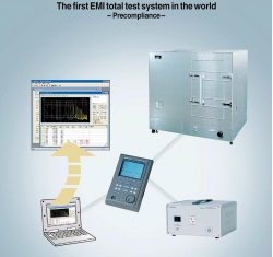
EMC EMI EMS TESTING SYSTEM MICRONIX MR2300
• The first EMI total test system in the world |
|
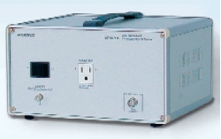
LINE IMPEDANCE STABILIZATION NETWORK MICRONIX MPW201
• The conducted emission discharged through the power supply line is measured by using the line impedance stabilization network (LISN). |
|
ELECTROMAGNETIC SHIELDING ANECHOIC BOX FOR EMI TESTING MICRONIX MY5310/ MY5410
• These two models using the ferrite tile as the radio wave absorber are optimum for EMI test |
|
SHIELDED ANECHOIC BOX FOR TESTING WIRELESS, CDMA, GSM MICRONIX ME8661A
• Optimum for testing W-CDMA, CDMA, GSM, PDC, PHS, ETC and wireless systems |
|
ELECTROMAGNETIC ANECHOIC BOX MICRONIX TAURUS-N MY1510N/ MY1520N/ MY1530N
• High quality and reliability the testing and measuring instruments manufacturer offers |
|
SHIELDED ANECHOIC BOX WITH ABSORBER FOR GSM TEST MICRONIX M8661B
• Equipped with the radio wave absorber covering 800MHz/900MHz frequency band |
|
ANECHOIC SHIELDING BOX FOR EMI & EMC RADIATIONS MICRONIX ME8669
• These are electromagnetic anechoic box using radio wave absorber of ferrite and ranging 50 to 800MHz |
|
HANDHELD SPECTRUM ANALYZER 50 KHZ..3.3 GHZ/ 8.5 GHZ MICRONIX MSA300
• 50kHz �3.3 GHz Frequency Range(model MSA338) |
|
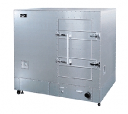
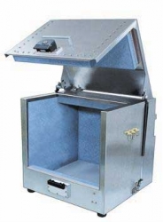
INDUSTRIAL ANECHOIC SHIELD BOX FOR MASS PRODUCTION MICRONIX MY5220
• Newest type of anechoic box with high shielding characteristics |
|
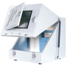
ELECTROMAGNETIC ANECHOIC BOX WITH LARGE WINDOW MICRONIX MY1520SW
• Large shield window for looking in anechoic shield box |