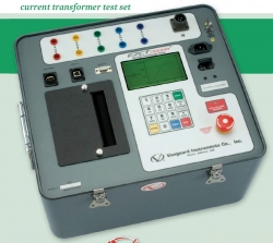
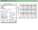
Trusa testare transformatoare de curent, raport transformare, excitatie, saturatie, polaritate Vanguard EZCT-2000A grafic curent-tensiunepolaritate infasurare bobinaj
Home |
Despre noi |
Noutati |
Promotii |
Reduceri |
Servicii |
Tech Library |
Cum comanzi? |
Harta site |
Contact
Testare transformatoare > VANGUARD (16) > Trusa testare transformatoare de curent, raport transformare, excitatie, saturatie, polaritate Vanguard EZCT-2000A
- Osciloscoape
- Multimetre
- Generatoare semnal
- Analizoare spectru
- Frecvențmetre
- Surse reglabile
- Sarcini electronice
- Analizoare logice
- Achiziții de date
- RLC-metre & Analizoare putere
- Analizoare calitate energie
- Testere instalatii electrice
- Aparate masura prize de pamant
- Clești ampermetrici
- Microhmmetre
- Testare transformatoare
- Truse incercari inalta tensiune
- Locatoare defecte cabluri
- Analizoare întrerupătoare
- Truse testare relee de protectie
- Testere baterii
- Analizoare solare fotovoltaice
- Testare retele cablu
- OTDR & Testere fibra optica
- Aparate sudura fibra optica
- Analizoare retele wireless
- Powermetre RF
- Analizoare TV si Satelit
- Generatoare Video
- Broadcast & Distributie TV
- Antene
- Amplificatoare semnal
- Testere camp electromagnetic
- Testere descarcare electrostatica
- Testare EMC & EMI
- Camere anecoice ecranate
- Calibratoare multifunctionale
- Calibratoare temperatura
- Calibratoare presiune
- Calibrare energie electrica
- Calibrare RLC
- Camere termoviziune
- Testere de mediu
- Testere sunet & vibratii
- Analizoare gaze
- Detectoare scurgeri apa
- Statii lipit – dezlipit
- Balanţe & Cântare
- Masuratori topografice
- Echipamente biomedical
- Microscoape
- Spectrometre
- Sisteme inspectie video
- Sisteme inspectie ultrasunete
- Sisteme training tehnic
Home |
Despre noi |
Noutati |
Promotii |
Reduceri |
Servicii |
Tech Library |
Termeni şi Condiţii |
Cum comanzi? |
Link-uri utile |
Harta site |
Contact |
Politica Cookie


Copyright © 2010 - 2025 / Distek


Copyright © 2010 - 2025 / Distek

 ROM
ROM ENG
ENG


