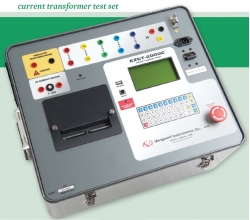
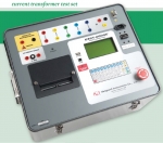
Current Transformer Test Set Turn Ratio, Excitation Curve , Saturation Graphic Vanguard EZCT-2000C Plus portable digital saturation plot graphic curve curent-voltage turn ratio excitation polarity

    office@distek.ro     ROM     ENG  
Login | Create account | Forgot password?
Product cart  Products: 0 | Total: 0    
 
 
    Home |  About Us |  News |  Promotions |  Discounts |  Services |  Tech Library |  How to order? |  Sitemap |  Contact
 
 
Products         [+ Expand]   [- Colapse]

Transformers Test > VANGUARD (16) > Current Transformer Test Set Turn Ratio, Excitation Curve , Saturation Graphic Vanguard EZCT-2000C Plus


  ..  Products navigator [3] from [16]    ..
 

Current Transformer Test Set Turn Ratio, Excitation Curve , Saturation Graphic Vanguard EZCT-2000C Plus

Code: Vanguard EZCT-2000C Plus
 
VANGUARD
 
 Product Datasheet (*.PDF - 1.09 Mb)

» Technical Specs

  • Performs CT excitation, current-ratio, polarity, and phase angle tests
  • Measures insulation resistance and winding resistance of the CT seconday windings
  • Measures the CT's secondary burden
  • Test record header information including company, substation name, circuit ID, manufacturer, CT serial number, operator name, and test record-comments
  • Built-in 4.5-inch wide thermal printer
  • Plot Multiple Saturation Curves
  • Stores up to 128 CT test plans and 140 test records internally
  • USB, Bluetooth, and USB Flash drive interface


The EZCT-2000C Plus is Vanguard’s third-generation microprocessor-based current transformer test set. Designed specifically for CT testing, the EZCT-2000C Plus has the following outstanding features that can greatly increase productivity and save time during the commissioning stage:

  • Performs CT excitation, current-ratio, polarity, and phase angle tests
  • Measures insulation resistance and winding resistance of the CT secondary windings
  • Measures the CT’s load burden
  • Standalone or computer-controlled via USB or Bluetooth wireless interface

The EZCT-2000C Plus’ test leads can be connected to all the CT output terminals, and the complete CT test can be performed automatically without any operator intervention.


Excitation Test

The CT excitation test is performed using the

ANSI/IEEE C57.13.1 test method. Test voltage

ranges from 50, 300, 500,1200 and 2000 Vac

can be selected for the excitation test. The test

voltage is raised and lowered automatically by

the EZCT-2000C Plus. The excitation test voltage

and current data is collected and stored in

the unit's internal memory. Knee point voltages

(ANSI 10/50, IEC 60044, IEEE-30, IEEE-45) are

calculated and printed on the test report. All of

the test leads can be connected to the CT output

terminals (X1, X2, X3, X4 and X5), and there is

no lead switching required during testing. This

convenient arrangement allows for testing any

of the 10 possible combinations of X1 to X5. Up

to 10 excitation tests can be stored in one record.

Once the test is completed, the test report

and CT excitation curves can be printed on the

built-in thermal printer.


Demagnetization

The EZCT-2000C Plus automatically demagnetizes

the CT under test when performing an

excitation test.


Winding Resistance Test

The EZCT-2000C Plus can measure the DC

resistance of transformer windings from 100

micro-ohms to 10 ohms.


CT Winding Insulation

Resistance Test Feature

The EZCT-2000C Plus offers an IR test feature

that can also measure the insulation resistance

of the CT’s secondary winding using a test voltage

up to 1000 Vdc. The DC winding resistance

reading range is from 2 to 500 Mega-ohms. The

insulation resistance test results are displayed

and printed on the report.


Ratio and Polarity Tests

The CT current-ratio is determined using the

ANSI/IEEE C57.12.90 measurement method. A

test voltage is applied on any two terminals (X1

to X5) of the CT, and the induced voltage is measured

through the H1 and H2 terminals of the CT.

The CT current-ratio is displayed and also stored

in memory. The current-ratio is measured from

0.8 to 5,000. The CT winding polarity is displayed

as a “+” sign (in-phase) or a “-” sign (outof-

phase) and is annotated with the phase angle

in degrees. The CT current ratio error and phase

displacement is also calculated based on the CT

burden (or rated power) and rated current.


CT Burden Test

The EZCT-2000C Plus can measure the CT’s actual

connected burden by injecting a 1A or 5A

test current into the load. The CT burden measurements

(Voltage, current, Cos φ, and burden

impedance) are displayed on the screen and

printed on the test report. This important test

verifi es the actual CT measured burden before

putting the CT in service, thus avoiding any potential

confi guration confl icts.


» Standard included accessories


Home |  About Us |  News |  Promotions |  Discounts |  Services |  Tech Library |  Terms and Conditions |  How to order? |  Useful links |  Sitemap |  Contact |  Politica Cookie

        
Copyright © 2010 - 2024 / Distek

Product: Current Transformer Test Set Turn Ratio, Excitation Curve , Saturation Graphic Vanguard EZCT-2000C Plus portable digital saturation plot graphic curve curent-voltage turn ratio excitation polarity